Current draw 0.5-1 A. dc motor. 5v power source. proFET
October 24, 2023, 23:46

Ok so I have a DC motor with a 3.7V battery which draws 0.5 A on normal load. Turning two rotor blades. It is from an old hover robot toy.
I have this https://www.infineon.com/dgdl/Infineon-BTS410E2-DS-v01_01-en.pdf?fileId=db3a304331c8f8560131dcc9fc520e21
That I use for switching. It requires 4.7V from the main power supply to operate. So I have replaced the battery with my own batteries. I have run it with 6 and 9 V batteries. On different occasions of course.
I switch it using one of the 3v3 gpio pins on the rpi4, gpio24. Works perfectly.
My question is this, would one of the 5V pins be able to support the current draw of the motor? I could try it I guess because I think the flywheel diode or some of the other protective features would protect the pie but I thought I could ask first just in case.
I was told that it wouldn't be able to support the current draw. My assumption is that if it can't it would result in a V-drop, making the FET inoperable. I have seen people using transistors with 3v3 pins where they used I=0.016A to calculate R to not damage the pin, but is that the hard limit for A both in and out on all pins?
Any way, again, could the 5V output support approx 0.5-1 A draw, when being hooked up via the FET in the link?

1. If you talk about Vbus (5v on the Pico), then its the USB power source that is the limit and of course, the Micro connector and the PCB traces on the Pico board.
2. Voltage drop. Since a motor is inductive it will cause inrush currents at start that will cause voltage drop and I would worry more about the Pico crashing. This can be solved with capacitors and filters or having separate power supply.
3. GPIO pin current, they supports a maximum of 16mA per GPIO pin with the total current from all pins not exceeding 51mA.
4. The BTS410 has Undervoltage and overvoltage shutdown with auto-restart and hysteresis so it will not be inoperable.
Ok 1, not using Pico. Only the raspberry pi 4.
2. You mentioned capacitors and filters to counter voltage drop. Out of curiosity, have you got a circuit diagram or link to video or something that explains this in more detail?
3 and 4. Does this mean that if I would use the power from one of the 5V pins to power the BTS410, and use a 3v3 pin to switch the BTS410; then the motor would spin very slowly or not at all, because the load of the motor requires orders of magnitude more current then it gets?
4. Address the "My assumption is that if it can't it would result in a V-drop, making the FET inoperable." The BTS has protection = No
3. Is an explanation of your comment "used I=0.016A to calculate R to not damage the pin" = Yes your correct
And as I see it BTS410 is a switch = On or Off, and the voltage for on/off is in the datasheet page 5
Yes, I am switching the input pin (2) with 3v3 gpio and have a battery at powersource Vbb (3)
I need to do some more research on the undervoltage and hysteresis. It looks to me, but may be completely wrong, that the hysteresis is charging the charge pump on page 13.
But in simple terms, if this undervoltage occurs, and the reset function is going on, will the noice from the motor risk "sending" high current into the hypothetical power source, 5V pin on the raspberry pi? Or do you mean the back EMS would "hit" the pin, because the BTS is in restart-state, and therefor will let current go back out through Vbb pin (3)?
Maybe it's something else, point is that I don't quite understand if you mean BTS will never protect the power source, not even during optimal operation conditions because of the noice, or that during the restart phase from undervoltage is when the BTS cannot protect power source. Without for example one of the solutions from the article.
Very interesting and educational article with video and diagrams btw, thanks!
You should have a flyback diode over the motor,

Sparkfun had a article about it a while back, https://cdn.sparkfun.com/assets/resources/4/4/DC_motor_circuits_slides.pdf
In the BTS, there is a flywheel diode directed in that way, I thought it would be enough. But should I have another around the motor as well?
The flyback over the MOSFET protects the MOSFET
And normally thats enough
You are correct there
And Im not familiar with the BTS, I have done my own circuits
Okay, that BTS is impressive, perhaps I should use it 🙂
Me neither, I was going to do it the transistor way, but then my father had some BTSes lying around. Since it had an n-channel FET in there with the fly wheel diode in it we figured it would be safe.
Then the problem was that the operating voltage was 4.7 V and the battery for the toy was 3.7 V, I think I experienced the undervoltage thing because I got a really slow moving motor.
Then I had the idea to use the 5V from the pi because it was above operational voltage. But then the current draw would be too high
The only advice I have is. Use short leads and a wire size that match the motor. The BTS has the protections you need to protect the power source and the RPi
There is a VDR that comes to mind if you don't need a "Fast" start of the motor. VDR is a Voltage Dependent Resistor, that would limit the current inrush even more than the BTS seems to do. VDR = From the start the resistance is high, and as the current flows through it it will heat up and the resistance is becoming lower.
But I think that is over engineering.
Ok I appreciate the concept of VDR, it seems a useful thing. It reminds me of a potentiometer, but adjusted by heat instead of a mechanical arm.
Yes, thats a good analogy
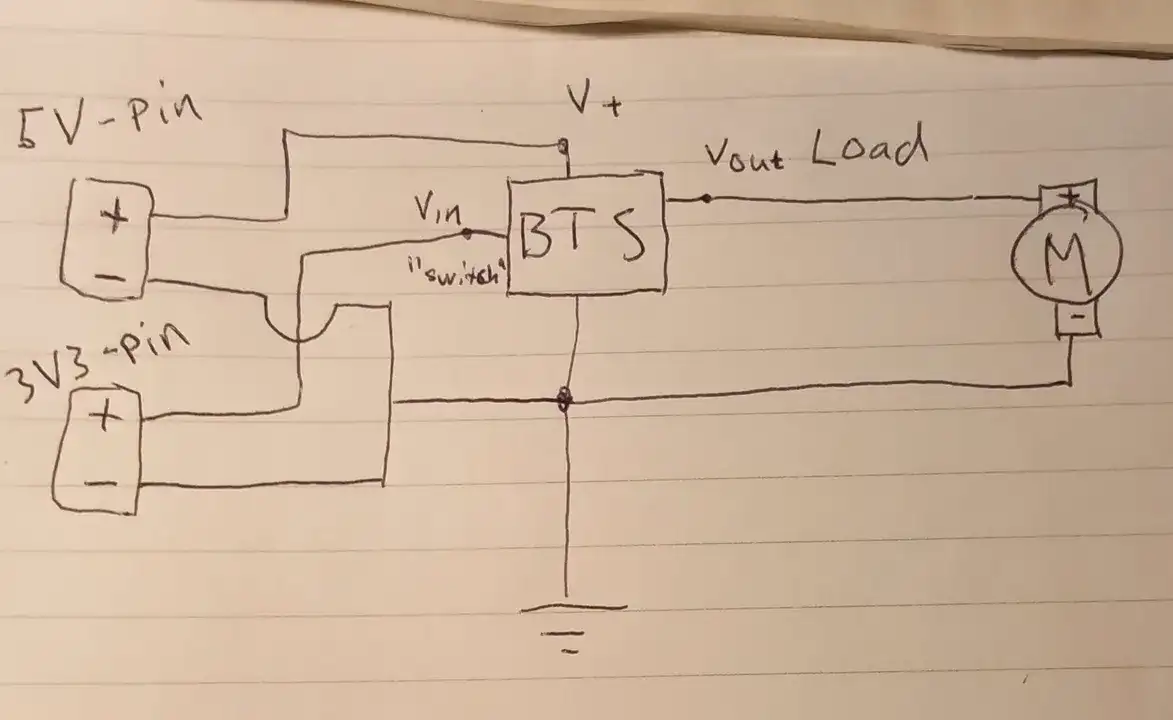
This diagram is not very professional but it describes, I hope, what I would like to be done. I drew the pins like batteries, but the - signs on the pins are of course groundpins in reality.
If you have a 6 volt battery instead of the 5V pin, that's the setup I have currently, which works fine with gpiozero-lib run from the pi.
So do you think I can try to change to how my diagram is? My hypothesis is that because of the limited current of the pins, it will not be able to spin the motor

I cant see that picture, you should crop it
Ok I'll try to fix the picture
With pins you mean 5V (Vbus)?
That should do it
I don't know if you see both the cropped and the little pinout of the raspberry pi
Im unsure what you ref to with "the little pinout of the raspberry pi", I clearly see the cropped picture where you use Vbus as 5v power and the 3,3 v as on/off power. A good test circuit to verify the operation.
But is it when you do that circuit that the motor is reacting slow?
This is how I would ideally would like to work. Blue is 5V pin for power the BTS. Green is 3v3 pin for switch

With the 3.7 V battery that came shipped with the toy as the power source, motor runs slowly through BTS
With a battery holder with 4 1.5V batteries in series, 6V, it runs lika a charm. Also with a 9V battery.
Note that I have never hooked the 5V pin as power source yet
If I just connect the motor to the 3.7V battery it works, but the operating V of the BTS being 4.7V, using the 3.7V battery should be undervoltages, no?
But because the motor draws 0.5 A at least, my hypothesis is that the 5V pin would not give enough current.
Now I believe it is at least safe to try it
It works! As I thought, it would be slower, but good enough for my intentions!
Thank you for your time, I have learned a lot!
"not give enough current".
Look at it this way. You have current producer and consumers. Producer = battery, power supply. Consumer = Motor.
If the consumer want 0,5A and the producer can produce 0,5A = No problem. The problem is when the consumer (motor) want to consume more than the producer can produce.
And your right to be cautious, if the infrastructure (USB micro, PCB copper and pins) between the producer and consumer is insufficient there will be smoke and fire or worse 😉
Oh, yes I see why this looked dangerous. Sorry, I just grabbed the closest wires and made a mental note
But it is a good idea to sort the wires, makes it easier to see what wire is doing what
Pheew 🙂
Now I have done more testing with less wires. First thing I noticed was the motor started spinning at a faster pace after a few seconds.
So I measured a little.
The motor pulls, 0.3A at on switch. Then it pulls 0.2A for 2-7 seconds. Then it starts pulling 0.85A. This seems to be stable all though I have not tested it for extended periods of time.
When it pulls the 0.85A, the 5V power drops to 4.69 (BTS pins 3 and 1).
Load V (BTS pins 5 and 1) is about 2 V at slow speed making R=10.something. At the higher speed it went up to 4.35 V making R=8.something ohm.
It says in the docs that load output current is self limiting. To me it kind of looks like the BTS has simply adjusted the resistance to get more current for the motor. I am not sure if this has to do with the charge pump or only dialed down the R. It feel like the effect of a VDR that you mentioned.
I also measured resistance of one of the wires it gave me 0.7 ohm. So it also makes sense that it would behave a little bit different with less of them.
Now I am planning to mount the motor back in the toy. I guess I have little choice but soldering. At least the ground wires.
I need the ground pin to attach to switch ground, power ground and motor ground. (I will not solder any thing on the pi don't worry 🙂 ). Have you got any tips for doing such a connection? Is the best option a lump of solder, or are there alternatives? Perhaps one of those regular plastic cubes with a little screw to fix the wires? I dont really know what options I have 🙂
You have pinpointed the options, and in Sweden we call the plastic cube for "sugar cubes" 😉 And sugar cubes or lump solder works
Haha yes I was not sure if they were called sockerbitar in english as well 🇸🇪 but ok then I will try sockerbitar först in case I want to change the design 🙂
Oops, your a Swed also 😉
Yes I am 🙂
Let me show you the wiring. It was my first project in electronics. I had a vision and I did it! But the wiring, very McGuyver.
It is currently dismantled because it was never meant to be a real thing. But I can use the motor in some other project. Maybe have some thing hoover etc.
Behold the wiring!

There are plastic "ropes", plastic straps, "kludd". The bts is "secured" by a shapened furniture protector plug.
Who has got time to buy things when you can use what ever things laying around?😁
I agree. Buying is overrated 😉